Description
A06B-6134-H303#A
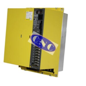
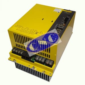
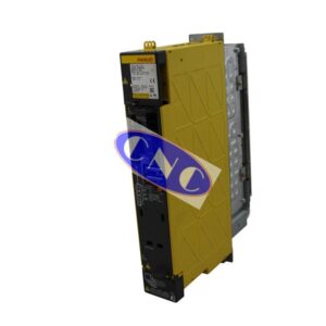
Fanuc A06B-6134-H303#A BETA amplifier combining reliable performance and stability. The biSVSP3-15i is a first attempt by Fanuc to create an energy efficient and capable combination servo spindle unit. CNC West offer exchange, test & repair of 200VAC triple axis 15kW BETA AC servo amplifier drive. Need a A06B-6134-H303#A today from our extensive stocks ?
Contact us now to get Fanuc Beta amplifier model Fanuc Beta iSVSP 40/40/40-15. Available today and ready to ship NOW to replace your faulty A06B-6134-H303#A displaying either servo, spindle or power related alarm codes.
This drive is part of the 200V series of Beta Amplifiers. With the following current output rating of 13amps on each axis and capable of running 15kW spindle motor.
We at CNC West have been repairing this drive for the last 11 years, and our group have been repair various Fanuc drives for considerably longer. Hence we can offer a quick 24 / 48 hour turnaround on repair at a reduced cost to our exchange service. Carrying parts such as fans, cases, plastic frames and front plates, as well various components allowing for a quick fix turnaround on 6134 series combo drive.
We have built our on custom test rigs for testing this Fanuc A06B6134H303#A with the correct size bi8 or bi12 Servo Motors and biLP18 spindle motors. System wise we use our in house 0i-MC rig which allows us to run full programs such as being on a CNC machine tool.
Interested in learning more? Contact us if you wish to discuss options for surplus, exchange or repair of your A06B-6134-H303#A module at (619) 477-9011 or by email at sales@cnc-electronics.net. We’d be happy to answer your questions!
If an alarm occurs in the servo amplifier and power section the ALM LED lights red in the STATUS 2 display and the single digit 7 segment LEDs indicate the alarm code
| 1 | Inverter: Internal cooling fan stopped |
| 2 | Inverter: Control power supply under voltage |
| 5 | Inverter: DC link under voltage |
| 6 | Inverter: Overheat |
| F | Inverter: Cooling fan stopped |
| 8. 9. A. |
Inverter: IPM alarm (L/M/N) |
| b, c, d |
Inverter: motor current alarm (L/M/N axis) |
| U |
Inverter: FSSB communication error (COP10B) |
If an alarm occurs in the spindle amplifier module the ALM LED lights red in the STATUS 1 display and the two digit 7 segment LEDs indicate the alarm code
| Alarm Code | Description of Alarm/Error |
| 01 | The inside temperature of the motor is higher than the specified temperature. |
| 02 | The actual motor speed is largely deviated from the commanded speed. |
| 06 | The temperature sensor is abnormal. Or the temperature sensor cable is broken. |
| 07 | The motor rotates at a speed exceeding 115%( standard setting) of the maximum allowable speed. |
| 09 | The temperature of the heat sink has risen abnormally. |
| 12 | An excessively large current flowed into the main circuit. This alarm indicates that the power module (IPM) of the main cicruit detected an error. Such as an excessive load or over current. |
| 19 & 20 | The offset voltage of the phase U (alarm code 19) or phase V (alarm code 20) current detection is excessively high. A check is made when the power is turned on. |
| 24 | Serial communication data transferred between the CNC and SVPM contain an error. (Note: This alarm is issued also if the CNC power is off. This is not a failure though) |
| 27 | The signal of the a position coder is disconnected. |
| 29 | An excessive load ( standard setting: load meter reading of 9.5V) has been applied continuously for a certain period (standard setting: 30 seconds) |
| 31 | The motor failed to rotate as specified and has stopped or is rotating at a very low speed. |
| 32 | LSI memory for serial communication is abnormal. A check is made when the power is turned on. |
| 41 | The position where the one rotation signal of the α position coder is generated is incorrect. |
| 42 | The one rotation signal of the α position coder is not generated. |
| 46 | The one rotation signal of the position coder cannot be detected normally during thread cutting. |
| 47 | The count value of α position coder signal pulses is abnormal. |
| 50 | A value obtained by internal calculation in spindle synchronization exceeded the allowable range. |
| 52 & 53 | The synchronziation signal ( ITP) in communication data transferred to and from the CNC stopped. |
| 54 | A large current flowing in the motor for a long time was detected. |
| 73 | The signal of the motor sensor is disconnected. |
| 75 | An abnormality was detected during control program transfer processing. |
| 79 | An abnormality was detected during control program initialization. |
| 81 | The position where the one rotatation signal of the motor sensor is generated is incorrect. |
| 82 | The one rotation signal of the motor sensor is not generated. |
| 83 | The SVPM checks the pulse counts of phases A and B each time a one rotation signal is detected. The alarm is issued when a pulse count beyond the specified range is detected. |
| 84 | The spindle sensor signal was disconnected. |
| 85 | The one rotation signal of the spindle sensor occured in an incorrect location. |
| 86 | No spindle sensor one rotation signal occured. |
| 87 | A spindle sensor signal is abnormal. |
| A1 & A2 | The control program is not running. An error was detected when the control program was running. |
| C0, C1 & C2 | An error occured in serial communication data between the CNC and spindle amplifier module. |
Do you need one of these drives ? Contact us if you wish to discuss options for surplus, exchange or repair of your A06B-6134-H303#A module at (619) 477-9011 or by email at sales@cnc-electronics.net. We’d be happy to answer your questions!